home work 14636585 2
Assignment
Digital Signal Conditioning
Work the problems below. To receive any credit, you must show all work. You may submit your work in a word processing document or in a pdf file. Graphic files are not acceptable submissions. Your file submission document should be entitled Week2AYourGID (replace YourGID with your specific GID).
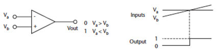
- A “1” signal is required to trigger an alarm, if the fluid level in a tank is more than 3m deep. The level sensor gives an output of 9.3mV for every centimeter increase in depth. What is the required alarm voltage?
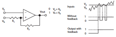
- In problem 1, if there are waves with amplitude of 35 cm due to pumping, what is the value of R2 to give a dead band with a 5-cm safety margin to prevent the comparator output from going low? Assume R1= 5k ohms, and output high = 5V.
- An 8 bit DAC has a reference voltage of 5V. What would be the voltage corresponding to a binary word of 10010011?
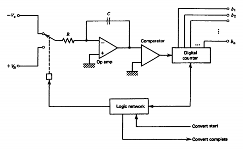
- What is the conversion time for the dual slope converter shown in the figure below if R = 1M ohm, C = 5nF, VR= 5V, integration time of 50 ms, and the input voltage is 8.2V? What is the capacitor discharge time?
- A temperature between -10 and +250 is converted into a 0- to 5.0 Volt signal. This signal is fed to an 8-bit ADC with a 5 Volt reference. What is the actual measurement range of the system? What is the resolution
Lab
Digital Signal Conditioning Lab
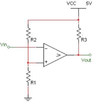
- For the comparator below, complete the design so that the threshold voltage is 1.25V which means that if the input is below 1.25V, the output will be HIGH and if its greater, it will be low. Once the resistance values are found, use Multisim to validate the design by applying a sine wave of 3Vpp into Vin and plot the results.
- Using the 8 bit Digital-to-Analog (VDAC) in Multisim, design the part with a 12V reference. Next apply the following inputs in the table below and both calculate and measure the output voltage. What is the resolution of the DAC? Show your circuit and results in Multisim.
| Digital Inputs | Calculated Analog Output Voltage | Measured Analog Output Voltage | |||||||
| 7 | 6 | 5 | 4 | 3 | 2 | 1 | 0 | ||
| 0 | 0 | 0 | 0 | 0 | 0 | 0 | 1 | ||
| 0 | 0 | 0 | 0 | 1 | 0 | 0 | 1 | ||
| 0 | 0 | 0 | 1 | 0 | 0 | 0 | 0 | ||
| 0 | 0 | 0 | 1 | 1 | 1 | 1 | 1 | ||
| 0 | 1 | 0 | 1 | 0 | 1 | 0 | 1 | ||
| 1 | 0 | 0 | 0 | 0 | 0 | 0 | 0 | ||
| 1 | 1 | 1 | 1 | 1 | 1 | 1 | 1 | ||
Do you need a similar assignment done for you from scratch? We have qualified writers to help you. We assure you an A+ quality paper that is free from plagiarism. Order now for an Amazing Discount!
Use Discount Code "Newclient" for a 15% Discount!
NB: We do not resell papers. Upon ordering, we do an original paper exclusively for you.